Do It Yourself Knowledge

Because life ain't cheap…

Archive for the ‘Engineering’ Category

Pin Gauges and Soddy Circles

Posted by diynovice on November 9, 2015

I have dealt with hand inspection over the past five years and I quickly learned how to check precision bores using three pin gauges. With extreme care, this method can save from having a custom gauge for every one-off bore that the engineers specify and allow for accurate measurement of small bores (less than 2 inches). The Machinists Handbook has a general formula that gives a simple way to find a set of three pins to use, however, it usually only gets you close, which is what a pair of calipers does. In a nut shell, I made my own Pin Gauge Finder program that will find the best set of three pin gauges in seconds for a desired bore size. You can find the program I made at the link below. Sorry for it being hosted on Source Forge, please be careful where you click.

https://sourceforge.net/projects/pin-gauge-finder/

Notes for the Pin Gauge user:

  • Pin gages are almost always 60 HRC (hardened steel) and have sharp edges. They can easily scratch softer materials as you slide them in a bore. Depending on the purpose of the bore, you may not want to use the three-pin method.
  • No pin gauge is exactly a given diameter, they each have an individual tolerance. Conveniently, working through the math, the outer Soddy circle diameter tolerance ends up being only 2 times the pin tolerance.

If you are interested in more information, please continue reading.

Background History
The history goes back to ancient Greece in the second century BC, with the Apollonus circle problem.  René Descartes first gave a solution in the 1600’s via a quadratic equation. Frederick Soddy rediscovered the solution in the 1930’s and published it in the form of a poem, The Kiss Precise, which described the solution to the special case of three circles all touching each other. The solution can be expressed neatly in terms of the curvature of the circles, k, which is the inverse of the radius:

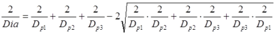
There are two possible solutions, the inner and outer Soddy circles, where the outer Soddy circle is essentially a bore. Rearranging the solution and replacing the curvatures with pin diameters [Dp1, Dp2, Dp3] gives the solution for the outer Soddy circle of diameter DiaDia will be a negative number as the three pins are internal to it.
SoddyEquation2
Before I go much further in how to solve this equation, we need to look at how many possible combinations there are for a given pin gauge set. This can be done by using the combination formula.

Where n is the number of pins available and k is the size of the group, in our case, 3 pins. Looking at a typical high quality pin gauge set where the maximum diameter pin is 25 mm, minimum diameter pin is 5 mm, and step size between pins is 0.01 mm, then there are 1,333,333,000 unique pin combinations. This is quite a large number for a standard computer to process, so further refinement needs to be done.

One can take the following steps to reduce the possible combinations to search:

  • Set Dp1 > Dp2 > Dp3
    • This ensures that only unique solutions (all 1.3 billion of them) are searched
  • Solve Descartes theorem for Pin 3  (Dp3)
    • SoddyEquation4
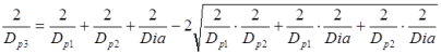
  • Focus on the square root
    • Dia is a given, so for any value of Dp1, one can find the maximum Dp2 value that keeps the term under the square root positive.
    • SoddyEquation6
  • Since Dp2 > Dp3, the minimum value of Dp2 is found by solving the Descartes theorem with Dp3 = Dp2.
    • SoddyEquation8
  • Focus on the pin range.
    • This is somewhat obvious. Don’t calculate if any pin falls outside the available pin range.

With this approach, for a given Dia, one can cycle through a small range of Dp2 pins for each Dp1 pin, and then only two or three Dp3 pins for each Dp2 pin. Overall, for the given pin range mentioned above, this brought the maximum number of iterations performed to 249,705; a much more reasonable number that can be performed in mere seconds.


The Beauty of it All
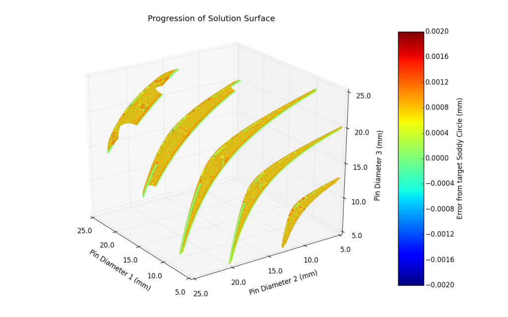
As I was optimizing the program, I noticed that the solutions tended to fall on a 3-dimensional surface. I plotted the solutions as a point cloud, with each axis representing a pin and each point colored based on its error. For a given diameter, the surface would intuitively move from one bounded corner to the other as shown below.

SoddyPicture1

Rotating the view to look normal to the surfaces, fascinating patterns are created.

SoddyPicture2

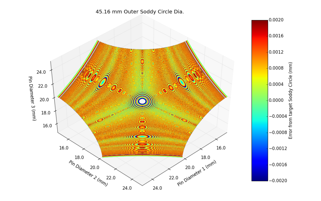
While I initially thought that the solutions fell on a sphere, it turns out they fall on some sort of 3-Dimensional 3-cusped hypocycloid. To illustrate this further, below is a video of the pin gauge set mentioned above, and the surfaces created from the range of outer Soddy Circles.

This just shows how unexpected things can come out of mundane efforts.


Fitting Points to a Sphere

I think it’s worthy to mention that while researching efficient ways to fit the solutions to a sphere, I stumbled on the below matrix technique[1] that works if you have a minimum of n=9 points:
SoddyEquation9
SoddyEquation10
where the coordinates of the sphere center [a,b,c] and sphere radius, R, are given by:
SoddyEquation11
This is an easy algorithm to program for large data sets and worked great as I was playing with large data sets (~30,000 points).


More information and useful links can be found here:

[1] Régressions coniques, quadriques, circulaire, sphérique. QUADRATURE. No. 65, July 2007. pg 4-5.

Descartes Circle Theorem on Mathworld

Marv Klotz’s Utilities – lots of useful DOS programs, including a brute force Plug.zip program that does the same thing but much slowly

Permutation Formula on MathWords

Combination Formula on MathWords

And bonus reading  (and maybe a future post) on Triangle centers:

Soddy Centers on Mathworld

Posted in Engineering | Leave a Comment »

Optimizing seating with Regiomontanus

Posted by diynovice on April 21, 2015

Reading ‘When Least is Best’ by Paul Nahin was quite a delight. This book has taken me on many tangents to explore the world of optimization. One path is the further exploration of the Regiomontanus angle maximization problem.

1-Regiomontanus_screen

This problem was posed in the 15th century, where it was known that if you stand too close to a painting (that is above you), it will appear small (such as if one was against the wall looking vertically up, you wouldn’t actually see the painting). And, stand too far away, and the painting disappears from sight. Paul solves the problem using the AM-GM inequality, a commonly used math tool before the knowledge of calculus. The solution to maximize the viewing angle, θ, as the originally posed question is:

2-equation1

An issue with the above solution is it assumes an infinite picture width.  In 1983, A. Tan and O. Castillo derived the solution to include a picture width as shown in the diagram above. This derivation showed that the original maximum θ and x-location were incorrect for a 2D painting. In their derivation, θ is the angle between the line-of-sight and the x-axis. Ω(x) is the angle that is swept across the image (i.e. the true viewing angle).

3-equation2

This is a complicated solution, no doubt. But this made me think. Most of the times when I view paintings on the wall or more commonly presentations, I rarely sit dead center. What would the viewing angle be if I was off-center?

Introducing a new variable, q, which is the distance away from the x-axis, the above limits of integration can be changed from ‘-b, b’ to ‘-b-q, b-q’, resulting in:

4-equation3

Contour plots of two examples are displayed at the end of this post where one can see that you just need to be in a small circle around the optimum point to see the largest image (the white area in the plot). The derivative of Ω with respect to x can also be made to obtain the maximum view for any given offset, q, which is presented as the purple line. This indicates that, at a minimum, you should stand or sit to the right of this zone. The angle of this region is about ±54° from the x-axis.

This is all fine and dandy, but digging deeper, when viewing a presentation, I find that I can move my body, neck, and head to various comfortable positions, and my eyes adjust to stare where needed. However, minimizing my eye movement seems to keep me awake during most presentations. Looking at anthropometric data posted on Learneasy.info, the optimum eye conical viewing angle is 30° and the approximate maximum eye conical viewing angle is 60°. Higher than 60°, and you will need to start rotating your head or body to view the screen. The limit of word recognition is 10-20°.

5-ergonomics

So, highlighting the 60°, 30°, and 10° viewing angles (the red line, yellow line, and green line respectively) can help understand where to sit during a presentation; which you are more likely to be viewing on a wall everyday. I personally like to sit in the 5° to 10° zone, I just never knew why until I started this derivation.

For the first example, a somewhat common projection screen size is used. The results show the screen will appear largest at 1.80 feet, which is awfully close. I would generally sit about 15 feet away, which corresponds approximately to a 10° viewing angle.

ViewAngle-4.5-4-1-table

ViewAngle-4.5-4-1


Looking at a common 60 inch television gives the below results.

ViewAngle-29-53-1-table

ViewAngle-29-53-1

Maybe the next step from here will be to include stadium seating. Then I could become a millionaire from creating an Optimal Conference Seating app.


References:

Nahin, Paul J. When Least is Best. Princeton University Press, 2011

Tan, A. and O. Castillo. Maximizing Paintings. The Mathematics Teacher, vol. 76, no. 7 (October 1983). Pg 472.

Posted in Engineering | Tagged: , , | Leave a Comment »

Moment of Inertia of Spherical Rings

Posted by diynovice on November 30, 2014

I recently needed to use the moment of inertia (MOI) of a spherical ring. Conveniently, the awesome Wolfram MathWorld website has the information I needed. An image of their spherical ring and MOI equation is below.

Spherical Ring - Figure1

Figure 1: Diagram and MOI as displayed on MathWorld’s site in 2012 (of course, I added the ‘wrong’ overlay to prevent it’s use)

However, after doing a simple thought-check, something seemed off. The moment of inertia of any axis of a solid sphere is (2/5)MR2. This means in figure 1, all three MOI terms should go to (2/5)MR2 when L equals 2R.

MOI(x) and MOI(y) do go to (2/5)MR2, however, MOI(z) goes to (8/5)MR2. Now, I’m second guessing myself as there are not many errors on MathWorld. But, if in the MOI(z) expression, the (+) was changed to a (-) then the MOI(z) would become (2/5)MR2. To confirm this is correct, lets derive MOI(z).

The general expression for the moment of inertia of any 3D object through its centroid is given in equation (1).

Spherical Ring - Equation1  (1)

Of course, (x,y,z) are coordinates and ρ is the material density. I am only interested in the z-axis expression, so the general form breaks down into (2).

Spherical Ring - Equation2  (2)

When looking at this problem, it is easier to find the MOI of a ‘solid’ spherical ring, and subtract the hole. These MOI’s are denoted Iz,b and Iz,c. The limits of integration are very similar to a normal sphere, except the integration in the z-direction only occurs for ±1/2L . These limits are:

Spherical Ring - Equation3 (3)

Spherical Ring - Equation4  (4)

Spherical Ring - Equation5  (5)

Evaluating equation (2) gives the MOI(z) of a spheric ring with a solid ‘hole’.

Spherical Ring - Equation6  (6)

The z-axis MOI of a cylinder is well known as:

Spherical Ring - Equation7  (7)

where r is the hole radius and m is the cylinder mass. These can be represented as r2 = R2 – ¼L2  and  m = ρπr2L.  With this, Iz,c is expanded to:

Spherical Ring - Equation8  (8)

Taking the solid Spherical Ring MOI and subtracting the cylindrical hole MOI gives:

Spherical Ring - Equation9  (9)

Spherical Ring - Equation10  (10)

Spherical Ring - Equation11  (11)

Equation (11) is the solution, however, to get MOI(z) into MathWorld’s notation, the density must be removed.

Spherical Ring - Equation12  (12)

Spherical Ring - Equation13  (13)

Spherical Ring - Equation14  (14)

Spherical Ring - Equation15  (15)

So, the MathWorld matrix should appear as:

Spherical Ring - Equation16

Being the dork that I am, I have contacted MathWorld multiple times with this derivation, however, the error still hasn’t been fixed. I am sure there are many more important things they have to do. In the meantime, hopefully this post will help the slim few who are looking for this information.


References:

Weisstein, Eric W. “Spherical Ring.” From MathWorld–A Wolfram Web Resource. http://mathworld.wolfram.com/SphericalRing.html

Posted in Engineering | Tagged: , , , , , | 1 Comment »

Volume of a Sphere (Ball) with an Off-center Hole

Posted by diynovice on December 2, 2012

A word of warning; if you couldn’t tell already, this is not a home improvement post, in the typical sense. However, it still is a DIY-type post (¿do calculus yourself…?).

A while ago, I wondered, what would the volume of a sphere be if an off-center hole was placed in it? I immediately had confidence that I had the mathematical knowledge needed to solve this problem symbolically (without using a computer). This is easy to do in a 3D modeling software, for a given sphere radius, and given hole radius, but that’s cheating! After an extensive online search, and multiple failed attempts at integration, I finally approached a math PhD, who told me, “unfortunately, this is a real world problem, with likely no solution”. This was discouraging, but I was determined!  I focused back on searching library journals until I found the complicated answer in a 1990 journal article. This made me feel better that the answer hadn’t been solved until relatively recently. I have put together this post with information that I have found along the way, so that, if the other two people with hole-in-sphere OCD like me, can rest easy.

In a mathematical sense, a sphere is a 3D surface of revolution of constant radius, where as, a ball is a sphere and the volume contained inside. Distinguishing between the sphere and ball can be important in the annals of Harvard and MIT, but not here. I will use the term sphere throughout this post as reference to a solid ball since it is more relate-able to most people…and to prevent (my own) adolescent jokes.

First, any straight line that intersects the surface of a sphere will always be parallel to the axis of the sphere. A sphere has a definite center-point and the sphere’s axes can freely rotate around that point to become parallel to the line, and the line will then be some distance from the center point (marked eccentricity below).
Sphere1
Putting a hole in a sphere, when the eccentricity is zero (the hole is centered) is easy to calculate. An interesting property of a centered hole in a sphere is that the volume of any sphere can be calculated if you know the height, h, of the hole (this is also known as the “Napkin Ring Problem”). Derivations of this can be found both at Mathworld and SFU.
Sphere2
For the above image, both volumes of the remaining spheres would be:
equation1
Remember, the volume of a complete sphere is:
equation2
In my opinion, the similar form is pretty remarkable. In terms of the Sphere radius, R, and hole radius, r, the volume can be displayed as:
equation4 where  equation3

Adding a hole eccentricity greatly complicates the volume integral that is used to obtain the above result. My first attempt to set-up and evaluate the equation is shown below, where I used a Spherical Coordinate system, a “pizza-slice” method, and an assumption that the eccentricity is less than the radius of the hole.
Sphere3aSphere3bSphere4

In this approach, the bore wall location is a function of the rotation, φ.
equation5
And, the integral can be written as:
equation6

The arc-cosine and the sine squared term ultimately prevent the integral from being evaluated.

The solution was finally found in a journal paper written by Francois LaMarche and Claude Leroy. The key to solving this problem is through the use of elliptical integrals.  The solution has standard elliptical integrals of the first, second, and third kinds, which can only be evaluated numerically (using a computer). But, it is a solution in a symbolic form (hooray!)
V(R,r,e) [remaining Sphere volume] =  equation7
The following terms are defined as:
Elliptical Integral of the First Kind:
equation8
Elliptical Integral of the Second Kind:
equation9
Elliptical Integral of the Third Kind:
equation10
And the other calculable terms:
equation11
equation12
              θ = Heavyside Step Function

There are two special cases where the above equations simplify and the elliptical integrals disappear.
Special Case 1: The hole is centered (e=0).
equation13
This is the same result as the integral performed at the beginning of this post.

Special Case 2: R=e+r
When R=e+r, the elliptical integrals disappear. When this case is true, the hole will always be tangent to the equator of the sphere, as in the picture below.
Sphere5
The volume can be represented in a number of ways, one of which is displayed below.
equation14
Viviani’s curve parameters, the 3D line or edge created on the surface of the sphere with the intersection of the cylinder, falls in this special case, however, it is defined precisely when R=2e=2r. The volume can then be further simplified to:
equation15

My OCD (obsessive curiosity disorder) certainly got the best of me on this problem. A lot of time has been spent solving this question, as it is not commonly sought.

References:
Weisstein, Eric W. “Spherical Ring.” From MathWorld–A Wolfram Web Resource. http://mathworld.wolfram.com/SphericalRing.html

DeBenedictis, Andrew. Volume of a sphere with a hole drilled through its centre. www.sfu.ca/~adebened/funstuff/sphere_cyl.pdf

LaMarche, F. & C. Leroy. Evaluation of the Volume of Intersection of a Sphere with a Cylinder by Elliptic Integrals. Computer Physics Communications. 59 (1990) 359-369.

Posted in Engineering | 2 Comments »

Spray Painting Galvanized Metal

Posted by diynovice on September 16, 2009

I recently made the mistake of promising my future wife that I could easily and cheaply spray paint a galvanized steel lantern we bought from IKEA.  After three cans of spray paint and a couple of lanterns, I found out I was dead wrong.  Now, I know a lot about metals, but I was never told that galvanized steel is difficult to paint.  So, this post is about galvanized steel, and ultimately, the only spray paint that will work on it.  For the readers who don’t care about the details, scroll down to the “**********” and continue reading.

Galvanized steel cannot be painted with normal alkyd-based paints, which almost all spray paints are based on (check the ingredients on the back of the can.  If there is any “alkyd…” don’t even think about using it).  Rust-o-leum is nice enough to put on the back of their spray paint cans to not use their spray paint on galvanized steel.  However, beware, most spray paint companies do not include this warning.

First, what is galvanized steel?  It is steel that has a zinc coating to increase the steels corrosion (rust) resistance.  Most galvanized steel is created by a process called hot-dip galvanization and a common characteristic of these steels is their display of  Spangle.  Spangle is just a fancy word for visibly large crystalline grain size.  Small amounts of lead and other impurities will increase the size of the spangle and make it more noticeable.  You can see the spangle in the galvanized steel guard rail below.
Guardrail
Other galvanization processes used to apply zinc coatings usually do not produce noticeable spangle but instead have a dull gray finish.  These processes are briefly described below (from Grip-Rite fasteners website):
Electrogalvanized – zinc coating applied to steel with an electric charge – offers limited corrosion resistance – typically applied to roofing nails
Mechanically galvanized– zinc applied by tumbling with powdered zinc and glass beads – provides slightly better corrosion protection than electrogalvaized steels.
Hot galvanized – zinc is applied through a heat treatment.  Provides best corrosion protection behind Hot-dip galvanization.

How does the zinc coating work?  The zinc coating provides corrosion protection by actively reacting with the atmosphere to form a thin, tough, inert layer of zinc carbonate to prevent the steel from rusting.  The zinc coating will also provide cathodic protection if the underlying steel is ever exposed (such as by a scratch).   While the zinc will always provide cathodic protection, it takes time for the zinc carbonate to form, and must undergo three transformations.  First, the zinc rich coating will react with oxygen in the air to form zinc oxide.  Second, the zinc oxide will react with oxygen and moisture to form zinc hydroxides.  Third, the zinc hydroxides will react with oxygen, moisture, and carbon dioxide to form zinc carbonate.

Depending on the atmospheric conditions that the galvanized steel is subjected to, the time required for each of these layers to form will vary.  Pure zinc will be present from 0 to 48 hours after the galvanization process; zinc oxides/hydroxides will form anywhere in 24 hrs to 2 years, and zinc carbonate will form in 8 months to 2+ years.  Galvanized steel exposed to the elements will quickly form zinc carbonate (within 8 months) whereas galvanized steel located indoors and not exposed to the elements, can take more than 2 years to fully form the zinc carbonate layer.  As the transformation advances, the surface will start to appear duller, but, the spangle of the surface will not be lost.

This is important for surface preparation, especially if you decide to brush paint and the steel is exposed to the elements.  The zinc oxides and zinc hydroxides are not well adhered to the surface and can easily chip off.  Zinc carbonate bonds well to the underlying zinc and provides an excellent painting surface.  More in depth details on the surface preparation for painting can be found on the American Galvanizers Association (AGA) website (see links at the end).   Rubbing the galvanized surface with a damp, lint-free cloth is most likely all that is required for the average DIY’er.  Oils can be present on the surface from the manufacturing process, however, items for indoor/home use should not have these oils.  Mineral spirits, turpentine, or vinegar can be used especially to remove any surface oils, however, these will leave a residue.  Be sure to thoroughly wash the surface to remove this residue if you choose to clean with one of these.

***********
Why can’t galvanized steel be spray painted?  Alkyld-based spray paints will react with the zinc during any stage of the galvanized layer, in a process called saponification.  The alkyd-base interacts with the zinc to form a soap at the interface.  This will result in poor paint adhesion and paint peeling.  Cold galvanizing spray paints will adhere to galvanized steel because of their high zinc content, however, top-coats of regular spray paints still will not adhere, and the colors of cold-galvanizing spray paints are very limited.

LatexMany brush-on paints exists to cover galvanized steel, but spray paints appear to be non-existent.  After much research, I finally found the solution.  Acryllic latex will adhere to galvanized steel with minimal surface preparation.  Therefore, the solution is Krylon’s H2O Latex spray paint.  It is an acrylic latex that will not chemically react with the galvanized surface.  [Krylon is one of the companies that does not include a warning against using their regular spray paints on galvanized steel.  Don’t be fooled.  All of their alkyd-based spray paints cannot be used on galvanized steel.  And, I don’t think they realize that they have the only spray paint that can be applied to galvanized steel.]  The spray paint costs about the same as any other spray paint and since it is a latex paint, it is more environmentally friendly.  It is difficult to find in stores.  I found it at Ace Hardware, but you can also find it from online retailers.  This spray paint is less viscous (more watery or runny) than the average spray paint, so use multiple light coats to prevent the paint from running and pooling on your project (I learned this the hard way).  DO NOT try to cover it in one coat.  The paint dries in about 15 minutes, however, the paint will not fully cure for about 7 days.  Also, do not use the Krylon H2O Latex primer.  It is alkyd-based (so technically, not a latex spray paint) and will not adhere, just like any other spray paint.

Hopefully, this information will help any future DIY’ers with their projects.  For more information, and more in depth explanation, visit the American Galvanizers Association’s (AGA) website at http://www.galvanizeit.org/ and check out their free publications on painting galvanized steel.

For general painting of galvanized steel, here is an excellent list of paints and their compatibility with galvanized steel.  This table comes from “Duplex Systems: Painting over Hot-Dip Galvanized Steel” which is available on the AGA’s website.

Type (paint base)…..Compatible…..Comments

Acrylics …….Sometimes……If the pH of the paint is high, problems may occur due to ammonia reacting with zinc
Aliphatic Polyurethanes…..Yes…..If used as a top coat for a polyamide epoxy primer, it is considered a superior duplex system
Alkyds…..No…..The alkaline zinc surface causes the alkyds to saponify, causing premature peeling
Asphalts…..No…..Petroleum base is usually not recommended for use on galvanized steel
Bituminous…..Yes…..Used for parts that are to be buried in soil
Chlorinated Rubbers…..Yes…..High VOC content has severely limited their availability
Coal Tar Epoxies…..Sometimes…..Rarely used, only if parts are to be buried in soil
Epoxies…..Sometimes…..If paint is specifically manufactured for use with galvanized steel
Epoxy-Polyamide Cured…..Yes…..Has superior adherence to galvanized steel
Latex-Acrylics…..Yes…..Has the added benefit of being environmentally friendly
Latex-Water-based…..Sometimes…..Consult paint manufacturer
Oil Base…..Sometimes…..Consult paint manufacturer
Portland Cement in Oil…..Yes…..Has superior adherence to galvanized steel
Silicones…..No…..Not for use directly over galvanized steel, can be beneficial in high temperature systems w/ base coat
Vinyls…..Yes…..Usually requires profiling, high VOC’s have severely limited their availability
Powder Coating…..Yes…..Low temperature curing powder coatings work exceptionally well over galvanized steel

Works Cited
American Galvanizers Association. (n.d.). Duplex Systems: Painting over Hot-Dip Galvanized Steel.Retrieved from American Galvanizers Association: http://www.galvanizeit.org 

American Galvanizers Association. (1999). Practical Guide for Preparing Hot Dip Galvanized Steel for Priming. Retrieved from American Galvanizers Association: http://www.galvanizeit.org 

Avallone, Eugene A., Theodore Baumeister III, eds. Marks’ Standard Handbook for Mechanical Engineers. 10th ed. New York: McGraw-Hill. Pgs. 6-93 & 6-110.

Grip-Rite. (2008, june). Grip-Rite Fasteners Catalog. Retrieved from http://www.grip-rite.com/fasteners.asp

Malone, J. F. (1992). Painting Hot Dip Galvanized Steel. Materials Performance , 31 (5), 39-42: http://www.galvanizeit.org

Peeling – From Galvanized Metal. (n.d.). Retrieved from Sherwin Williams: http://www.sherwin-williams.com/pro/problem/problems/peeling_galvanized/index.jsp

Painting Galvanized Steel. http://www.galvanizingasia.com/pdfs/page65-69.pdf

Why does Rustoleum Rusty Metal Primer say not to use on galvanized metal?
. (2008, May 8). Retrieved from Handy Man Club: http://www.handymanclub.com/Community/Forums.aspx?g=posts&t=38018

Posted in Engineering | 149 Comments »